Image-matching: Locating Imagery in 3D Space
Maksym Rokmaniko, The Center for Spatial Technologies
Jump to:
Part 1: Setup: Software Requirements | Data Downloads Part 2: Building the Base Model:
Creating a Base Model with DEM and Satellite Imagery
Setup project coordinate system |
Export GIS data for model |
Building Mesh model with Blender |
Alternative Methods to Build the Base Model
© Center for Spatial Technologies
In this tutorial, we'll explore how to use the image-matcher Blender add-on to locate 2D images within a 3D model. This technique is crucial for our ongoing work at the Center for Spatial Technologies, where we've applied it to various projects.
We've used and evolved this method to document and analyze sites of significant historical and current events, including:
• Babyn Yar• Russian attack on Kyiv TV tower
• Missile strike on Mykolaiv ODA
• Mariupol Drama Theater
* Currently, CST team applying this technique to the Chersonesus archaeological site in occupied Crimea. This UNESCO World Heritage Site is being manipulated for Russian national myth-building, with rushed construction and ideologically-driven excavations causing irreversible damage. *
* By precisely positioning photographs and drone footage in a 3D model, we can document these changes, providing vital evidence of cultural heritage destruction. In this tutorial we will learn to create a base 3D terrain model, match various imagery types to it, and create animations between matched positions. While we use Chersonesus as our case study, these skills can be applied to any site requiring accurate documentation and analysis. *
Setup
Software Requirements
To follow this tutorial, you'll need to have the following software installed:
1. Blender (version 3.0 or newer): Blender is a free and open-source 3D creation suite. Download it from blender.org. We will use Blender 4.2.
2. Image-matcher Add-on for Blender: This custom add-on enables precise image matching in Blender. You can download it from our GitHub repository.
3. Blender-GIS add-on for Blender: This add-on enables the import and manipulation of geospatial data in Blender. Download it from the BlenderGIS GitHub repository.
4. QGIS (latest stable version): QGIS is a free and open-source geographic information system. Download it from qgis.org.
Ensure all software is installed and functioning correctly before beginning the tutorial. If you encounter any issues with installation or setup, please refer to the documentation for each software.
Data Downloads
For this tutorial, you'll need several types of geospatial data to create a 3D model and match 2D images to it. Download the following datasets:
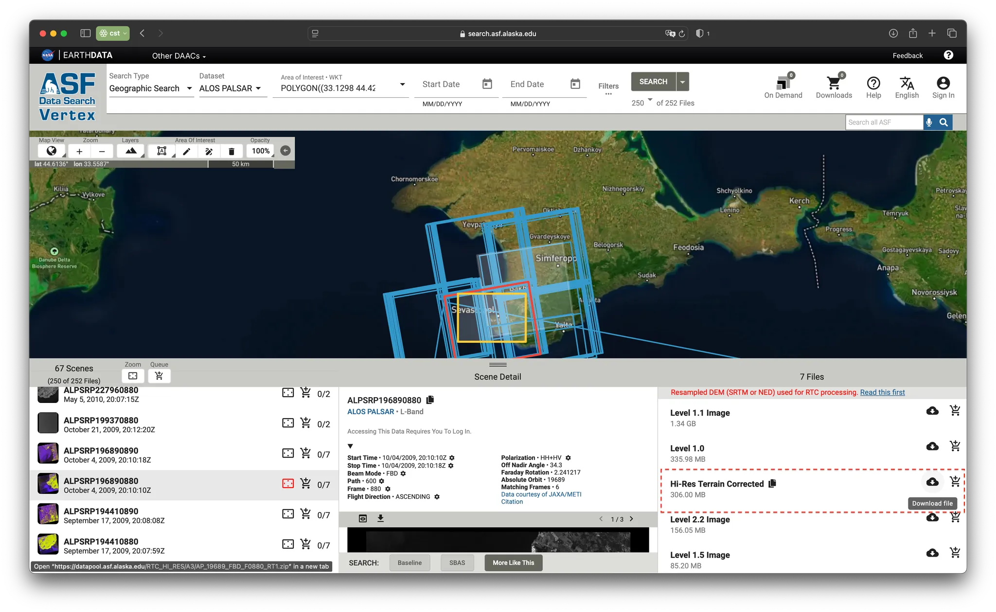
1. ALOS PALSAR Radiometric Terrain Corrected (RTC) Data: This high-resolution digital elevation model (DEM) is derived from radar data. Source: Alaska Satellite Facility (ASF) Data Search.
2. High-resolution Satellite Imagery: Recent high-resolution imagery of your study area.
3. Drone Footage: Aerial imagery captured by drones over your study area.
4. Ground-level Photographs: Photographs taken at ground level of key areas in your study site.
5. Photogrammetry Model (optional): A detailed 3D model of specific structures within your study area.
To make it easier to follow along with this tutorial, we've prepared a sample dataset that includes all necessary files for the Chersonesus site. You can download this dataset here:
Download Sample Dataset (sample_image-match_data.zip)
Building the Base Model
In this tutorial, we will demonstrate the use of the Image-Matcher Add-on for Blender by using the example of aerial photographs around a large-scale archaeological site. This technique can be applied in various contexts and across different model scales, including architectural, interior, and object models.
If your primary interest is learning how to use the Image Matcher tool, you can skip the section on building the base model, directly towards Image-matching, as this is only one possible use case for the tool. The add-on is versatile and can be applied to a wide range of scenarios, enabling precise image alignment and location on both small and large-scale models.
Creating a Base Model with DEM and Satellite Imagery
A Digital Elevation Model (DEM) provides essential elevation data for 3D terrain modeling.
Several options for obtaining DEM data, depending on your project’s location and requirements:
1. Provided DEM for Chersonesus: You can use the provided .tif file for the Chersonesus site, which contains high-resolution elevation data for the area.
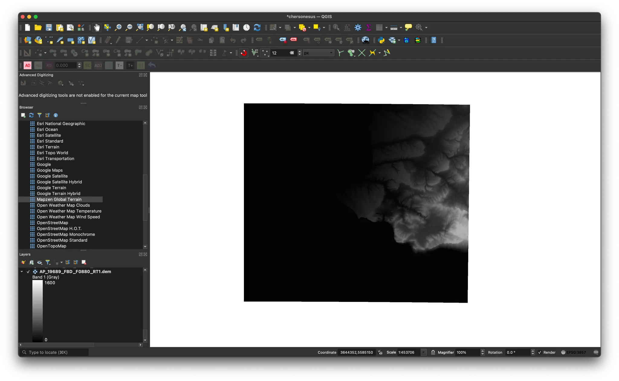
2. ALOS PALSAR DEM: For other regions or more detailed elevation data, you can download high-resolution DEMs from the Alaska Satellite Facility (ASF). Go to ASF Data Search, select the Hi-Res Terrain Corrected data, and download the .tif file for your area of interest.
3. Mapzen Terrain Tiles: As an alternative, you can use the Mapzen Terrain Tiles dataset, a public source for global elevation data. This tiled dataset offers lower-resolution but easily accessible DEMs, which can be added to QGIS via XYZ-tile connection. Simply configure the URL (https://s3.amazonaws.com/elevation-tiles-prod/terrarium/{z}/{x}/{y}.png) in the XYZ-tile connection dialog in QGIS to load global elevation tiles.
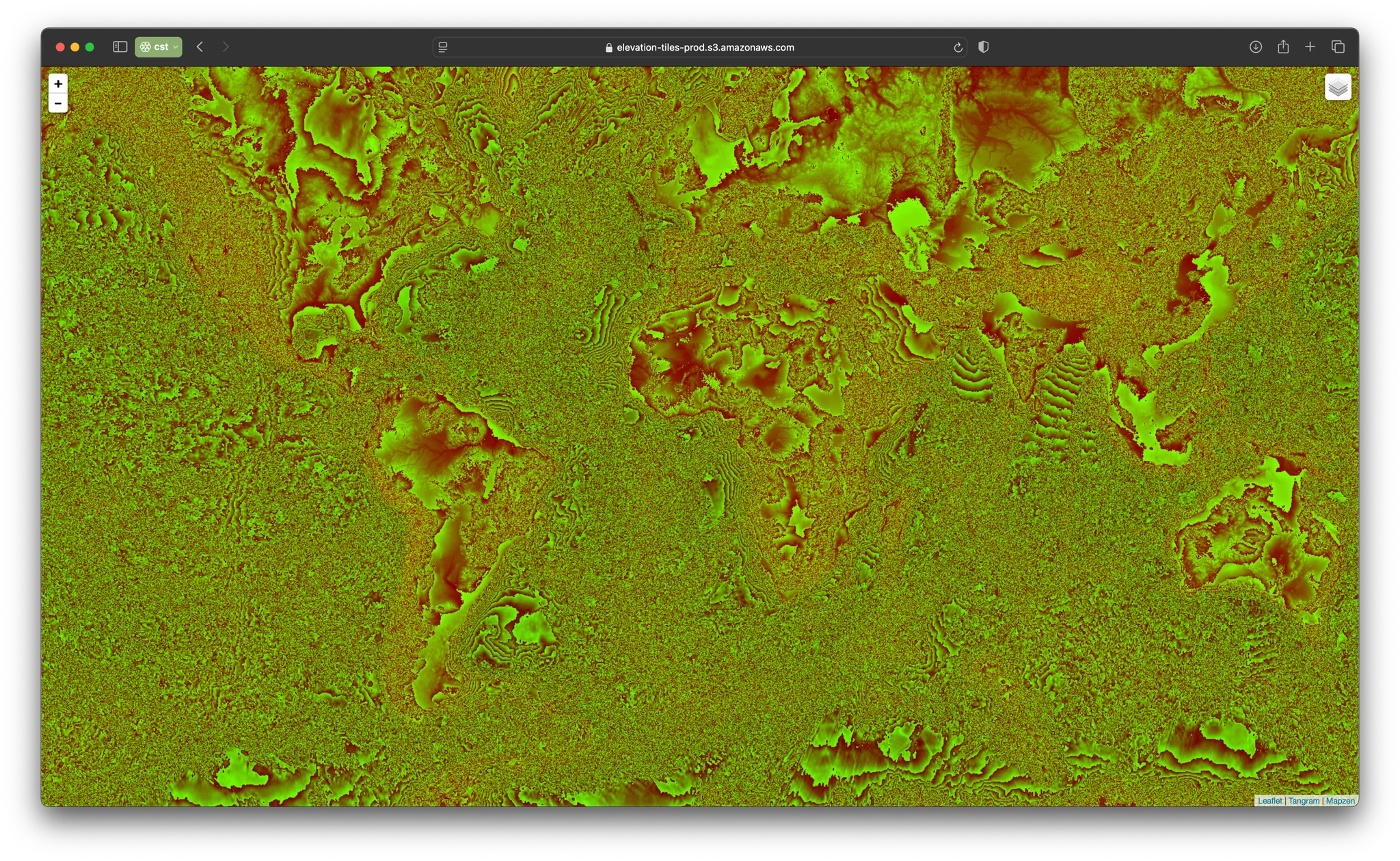
Mapzen Terrain Tiles ( Public Dataset)
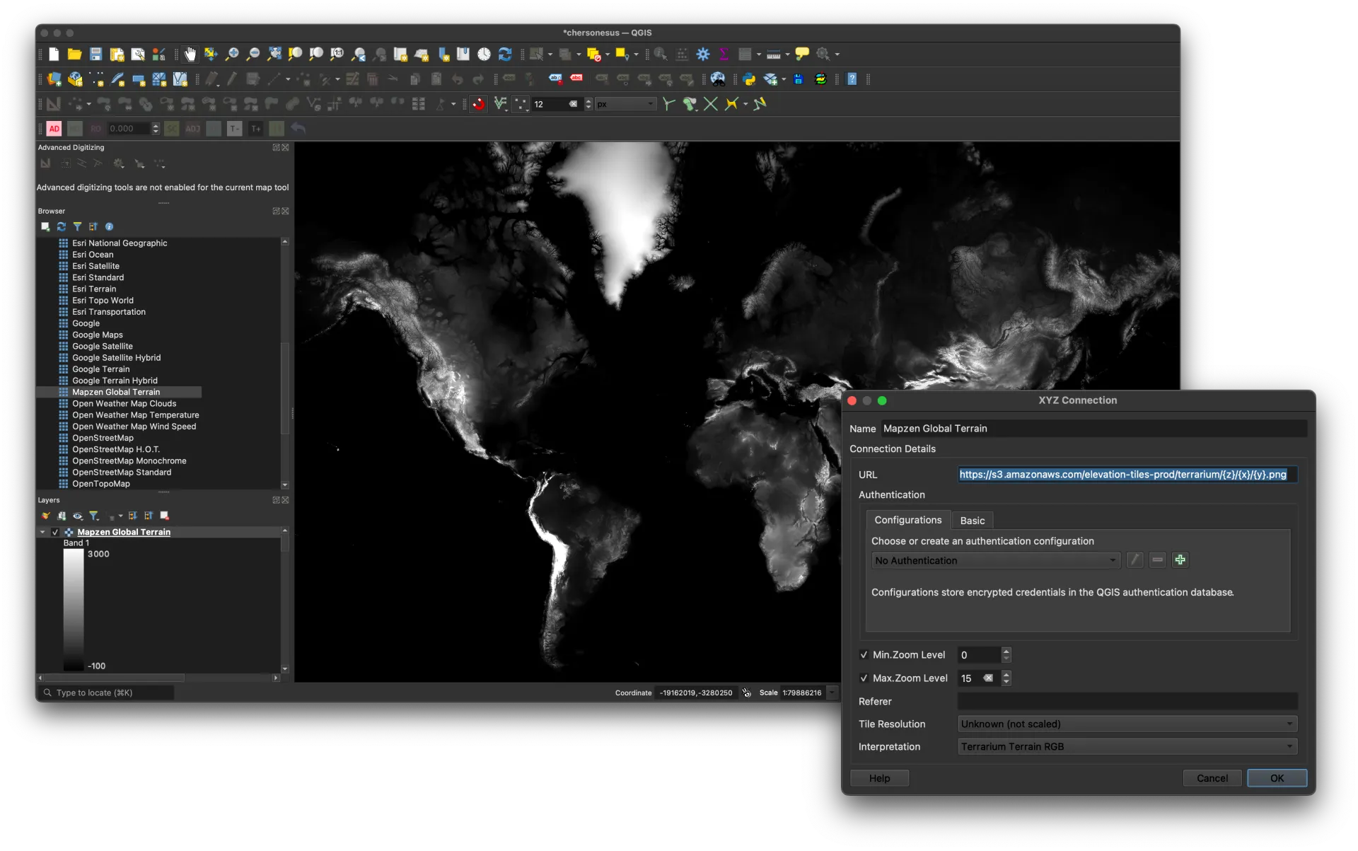
QGIS XYZ-tiles connection configuration
When using satellite imagery, select images captured as close to nadir (directly overhead) as possible. This approach minimizes distortions, especially in areas with varied terrain, reducing the need for complex orthorectification and ensuring a more accurate 3D landscape representation.
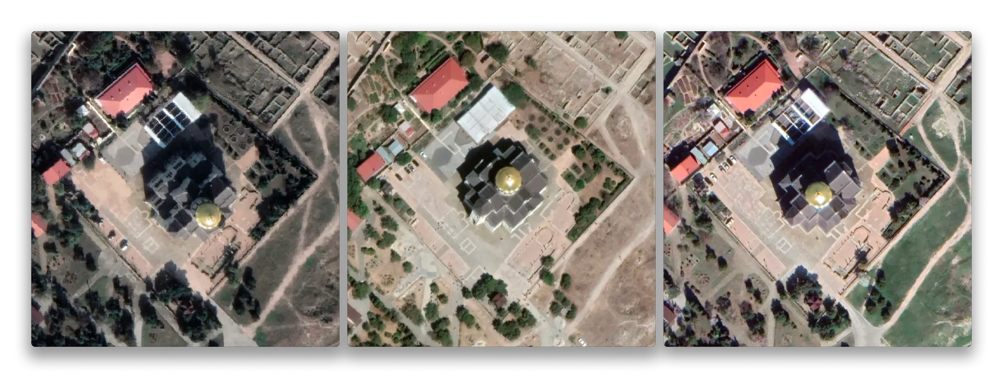
Evaluating satellite imagery for base model texture
When evaluating satellite imagery for your model, consider the terrain’s impact on image quality:
1. Poor Quality: Significant terrain relief causes noticeable distortions. Steep slopes and tall structures may appear skewed or stretched.
2. Acceptable Quality: Less terrain influence, but some distortion still visible on slopes and taller objects.
3. Ideal Quality: Minimal terrain-induced distortion. The image appears flattened, with vertical elements and slopes accurately represented.
Select and import your satellite imagery into QGIS
With the Digital Elevation Model (DEM) and satellite imagery layers prepared, we are ready to proceed to the next step: building the geometry. This step will involve overlaying the DEM with the satellite imagery to create a textured 3D model, accurately reflecting the terrain’s historical features.
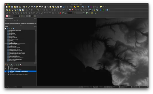
Heracles Peninsula DEM tileset. @Mapzen tiles, 2024
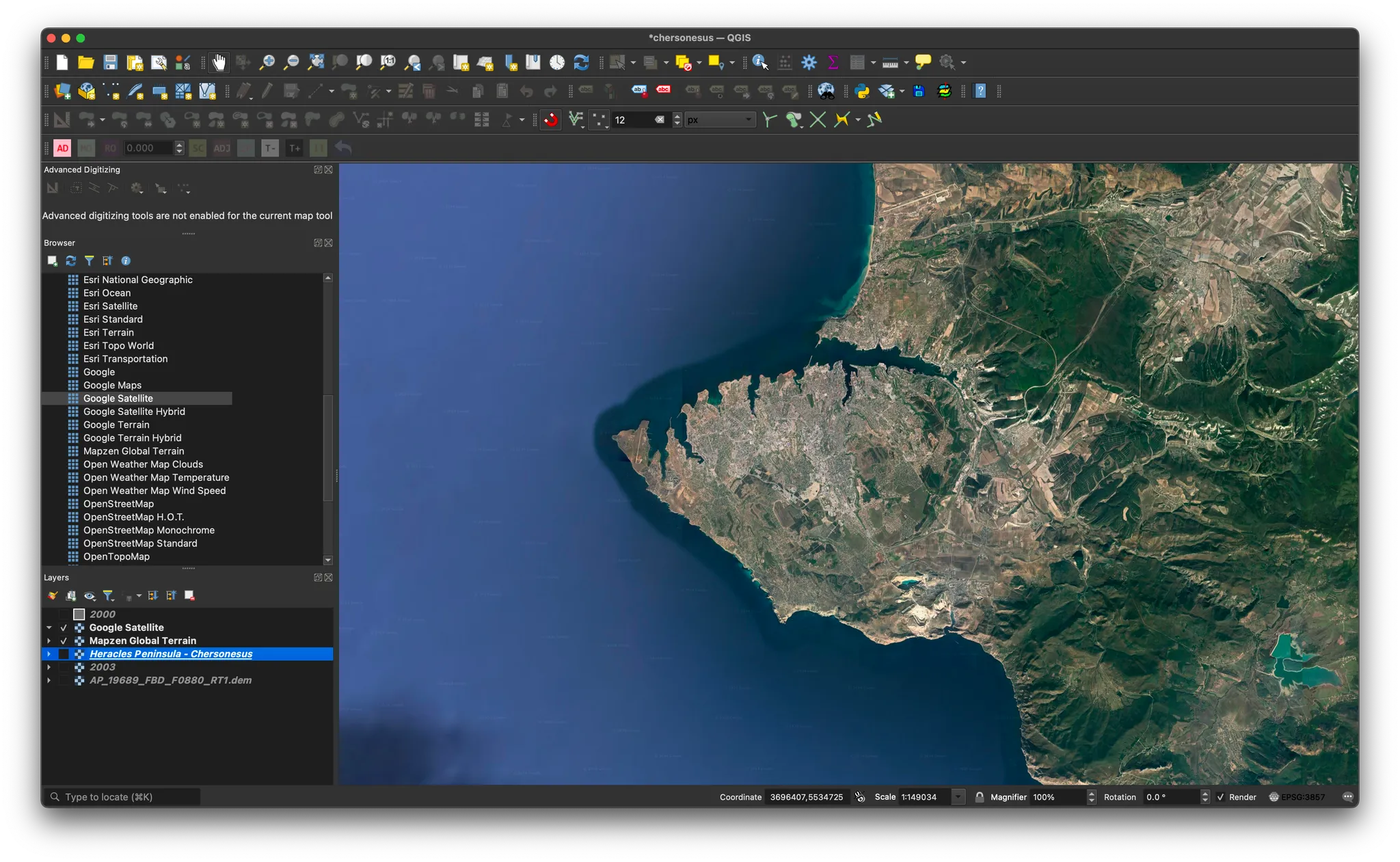
Heracles Peninsula Satelite image. @Google Earth, 2022
Setup project coordinate system
For this image-matching tool tutorial, we'll focus on the Ancient City of Tauric Chersonese site and its buffer protected zone.
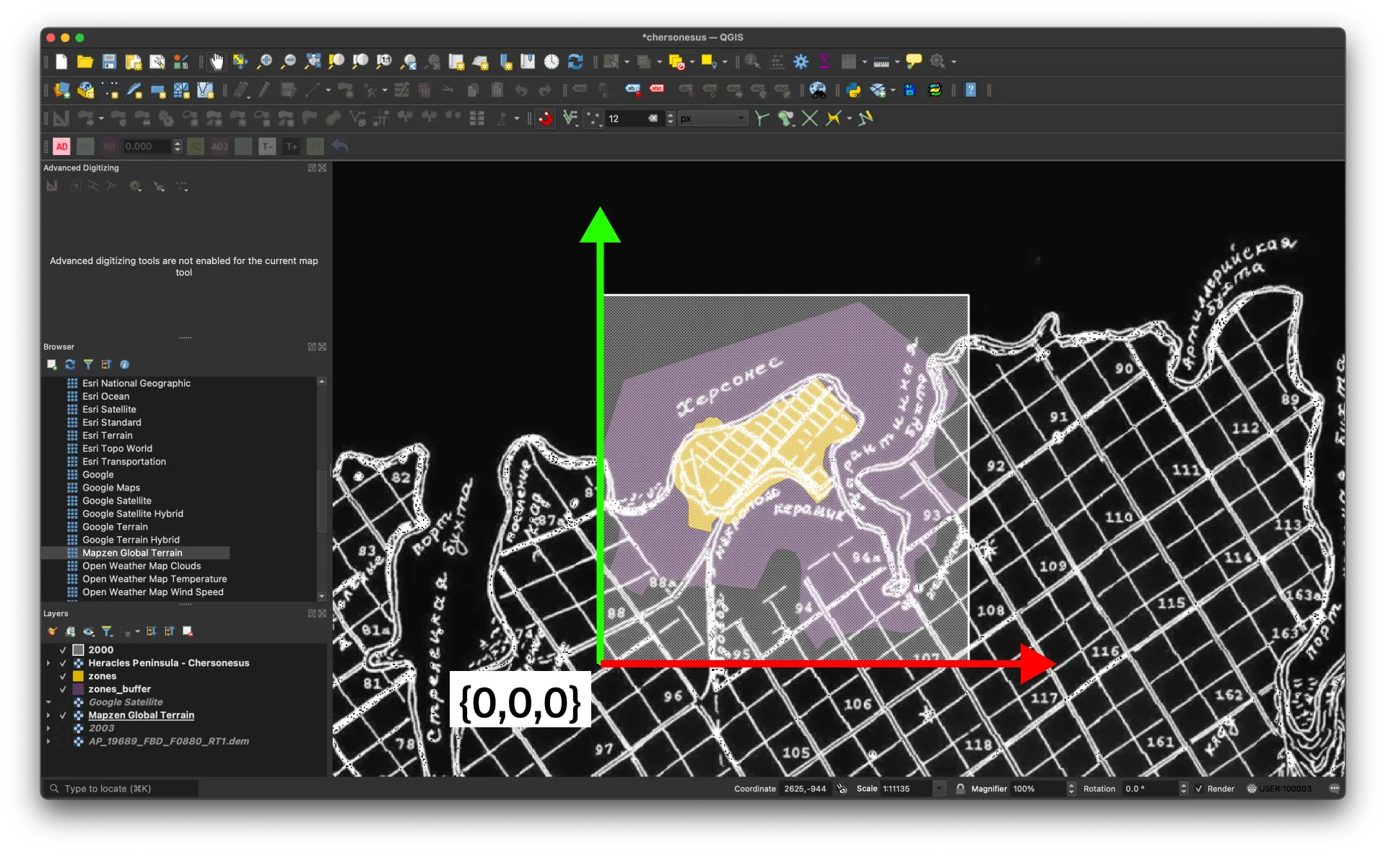
The Ancient City of Tauric Chersonese and its buffer zone
When zooming in on a particular site, we recommend defining a local coordinate system for 3D modeling and coordination. While optional, we prefer to derive an offset local coordinate reference system (CRS) from the defined regional one. In this case, we'll use UCS-2000 / 3-degree Gauss-Kruger zone 11 as the CRS for this area.
We'll define a 2000x2000 meter square domain for our model, with a user coordinate system UCS-2000 / Chersonese originating in the square's bottom-left corner.
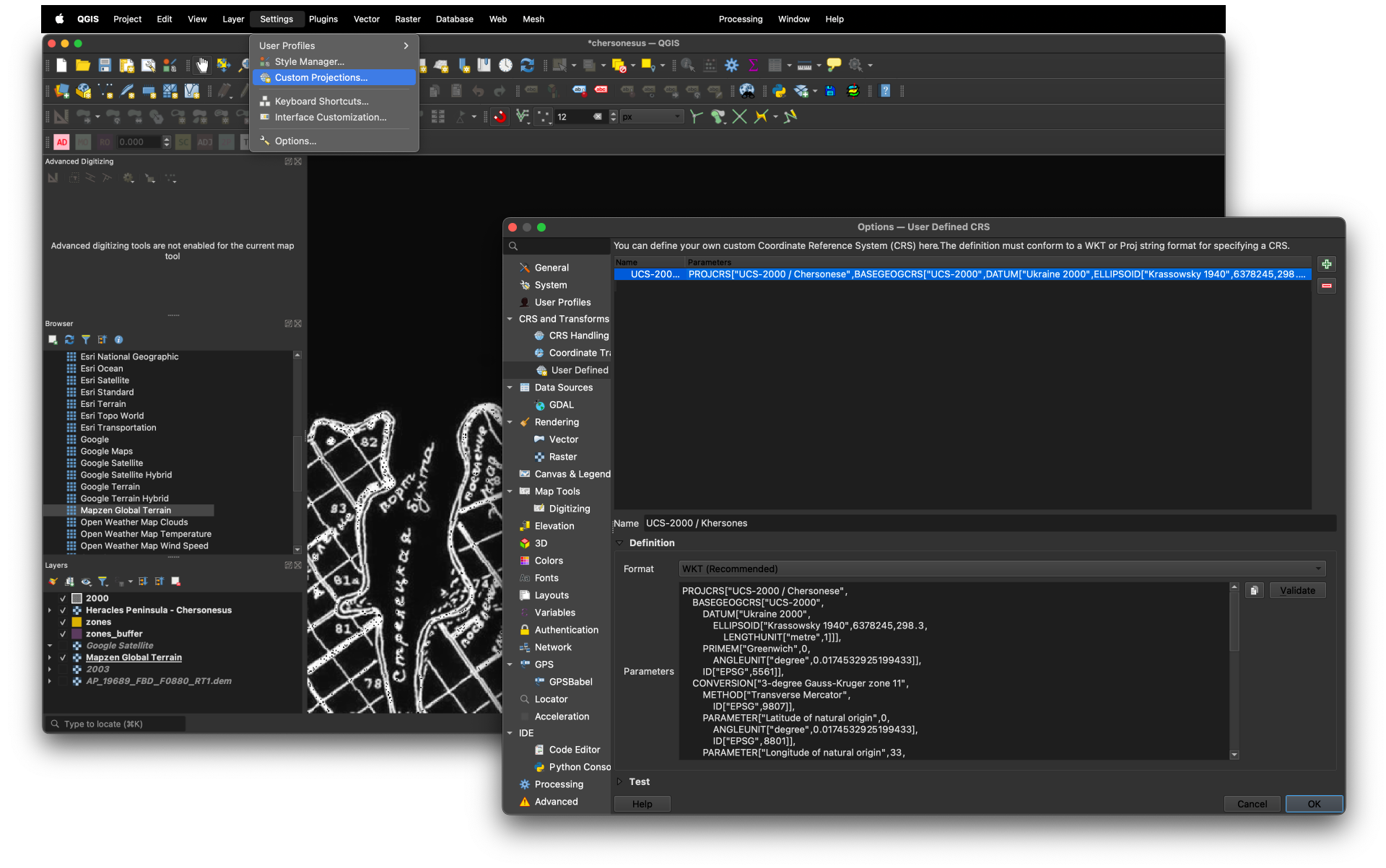
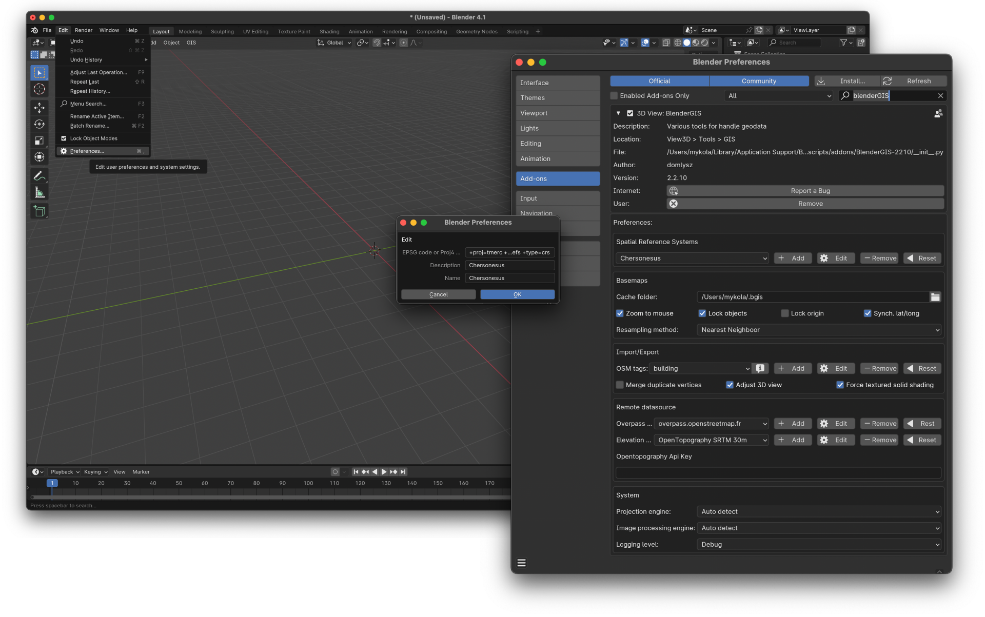
Define Custom CRS
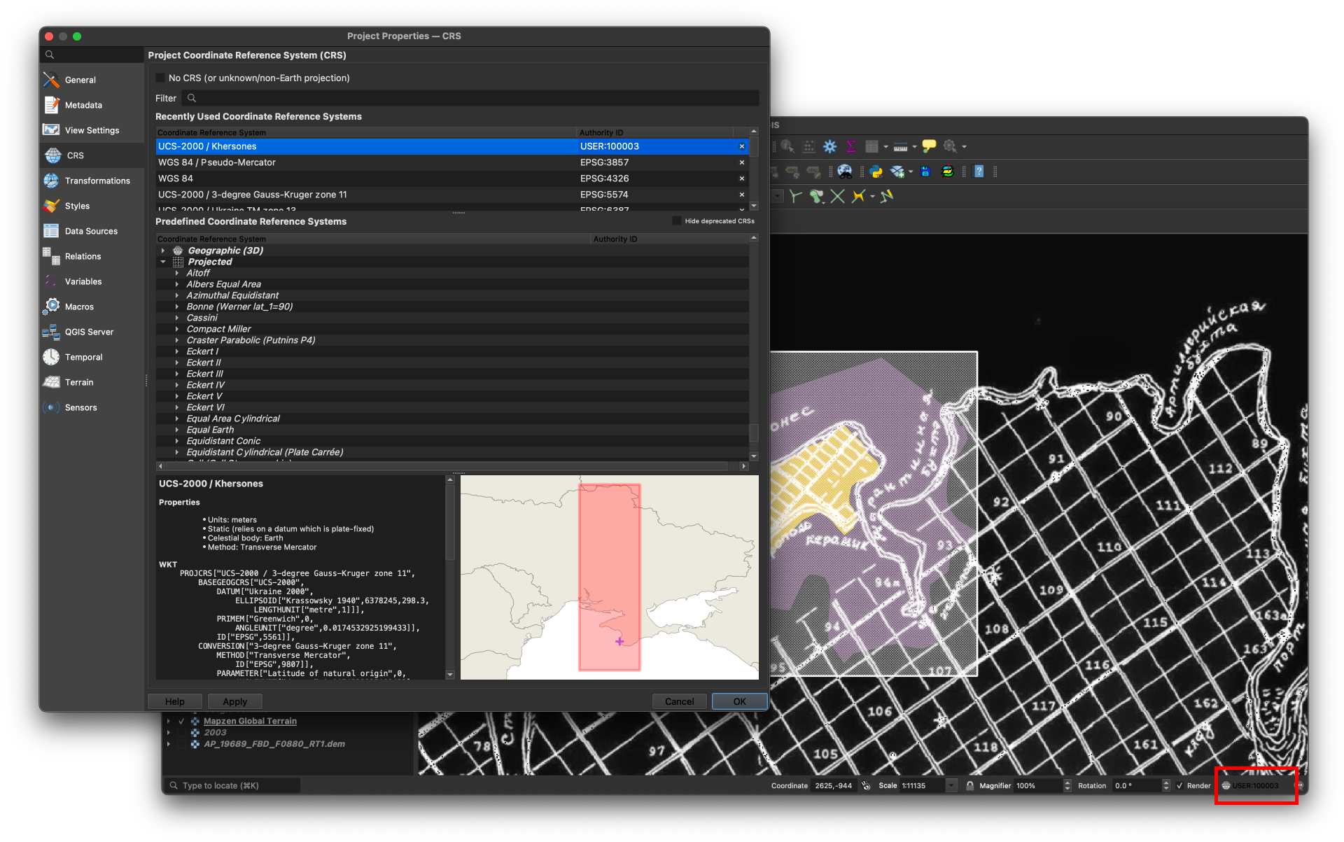
Select User-Defined or suitable general CRS for your geographic area
    PROJCRS["UCS-2000 / Chersonese",
    BASEGEOGCRS["UCS-2000",
        DATUM["Ukraine 2000",
            ELLIPSOID["Krassowsky 1940",6378245,298.3,
                LENGTHUNIT["metre",1]]],
        PRIMEM["Greenwich",0,
            ANGLEUNIT["degree",0.0174532925199433]],
        ID["EPSG",5561]],
    CONVERSION["3-degree Gauss-Kruger zone 11",
        METHOD["Transverse Mercator",
            ID["EPSG",9807]],
        PARAMETER["Latitude of natural origin",0,
            ANGLEUNIT["degree",0.0174532925199433],
            ID["EPSG",8801]],
        PARAMETER["Longitude of natural origin",33,
            ANGLEUNIT["degree",0.0174532925199433],
            ID["EPSG",8802]],
        PARAMETER["Scale factor at natural origin",1,
            SCALEUNIT["unity",1],
            ID["EPSG",8805]],
        PARAMETER["False easting",-38220,
            LENGTHUNIT["metre",1],
            ID["EPSG",8806]],
        PARAMETER["False northing",-4940800,
            LENGTHUNIT["metre",1],
            ID["EPSG",8807]]],
    CS[Cartesian,2],
        AXIS["northing (X)",north,
            ORDER[1],
            LENGTHUNIT["metre",1]],
        AXIS["easting (Y)",east,
            ORDER[2],
            LENGTHUNIT["metre",1]],
    USAGE[
        SCOPE["Heritage site violations documentation, high-precision surveying, and 3D modeling of Tauric Chersonese."],
        AREA["Ukraine, Crimia. Ancient City of Tauric Chersonese."],
        BBOX[44.60, 33.48,44.62, 33.51]]]
UCS-2000 / Chersonese CRS definition
Using this local coordinate system allows for easy conversion between local Blender model data and world/GIS contexts.
Export GIS data for model
Create an area of interest (AOI) polygon
Before clipping the DEM and satellite imagery, you need to define the Area of Interest (AOI). Follow these steps to create an AOI polygon:
1. Create a New Shapefile Layer (Vector Layer):
• In QGIS, go to the top menu and select Layer > Create Layer > New Shapefile Layer…
• In the dialog box, choose Polygon as the geometry type.
• Set the CRS to your custom CRS (or the regional CRS).
• Name the file (e.g., 2000.shp) and save it.
2. Draw the AOI Polygon:
• Select the Toggle Editing button for the new shapefile layer in the Layers panel.
• Click the Add Polygon Feature tool from the toolbar.
• Draw a rectangle covering your 2000x2000m area of interest by clicking on the map canvas or using advanced digitizing tools.
• Press Enter or Right Click to finish the polygon and save the shapefile.
3. Save and Exit Editing Mode:
• After drawing the polygon, click Toggle Editing again, and choose Save when prompted.
Clip and export selected layers
There are two option we can save clipped region:
1. Clipping raster Raster > Extraction > Clip Raster by Mask Layer.
2. Export layer with clipping boundaries Right-Click on the Raster Layer in the Layers Panel > Select “Export” > “Save As…”
While the “Clip Raster by Mask Layer” method generally offers better precision and higher quality, we recommend using it for most clipping tasks. However, when working with raster tiles, this method may not be supported. In such cases, we suggest using the “Export” > “Save As” option, which is more suitable for clipping tiled datasets or formats that don’t allow the use of the “Clip Raster by Mask Layer” tool.
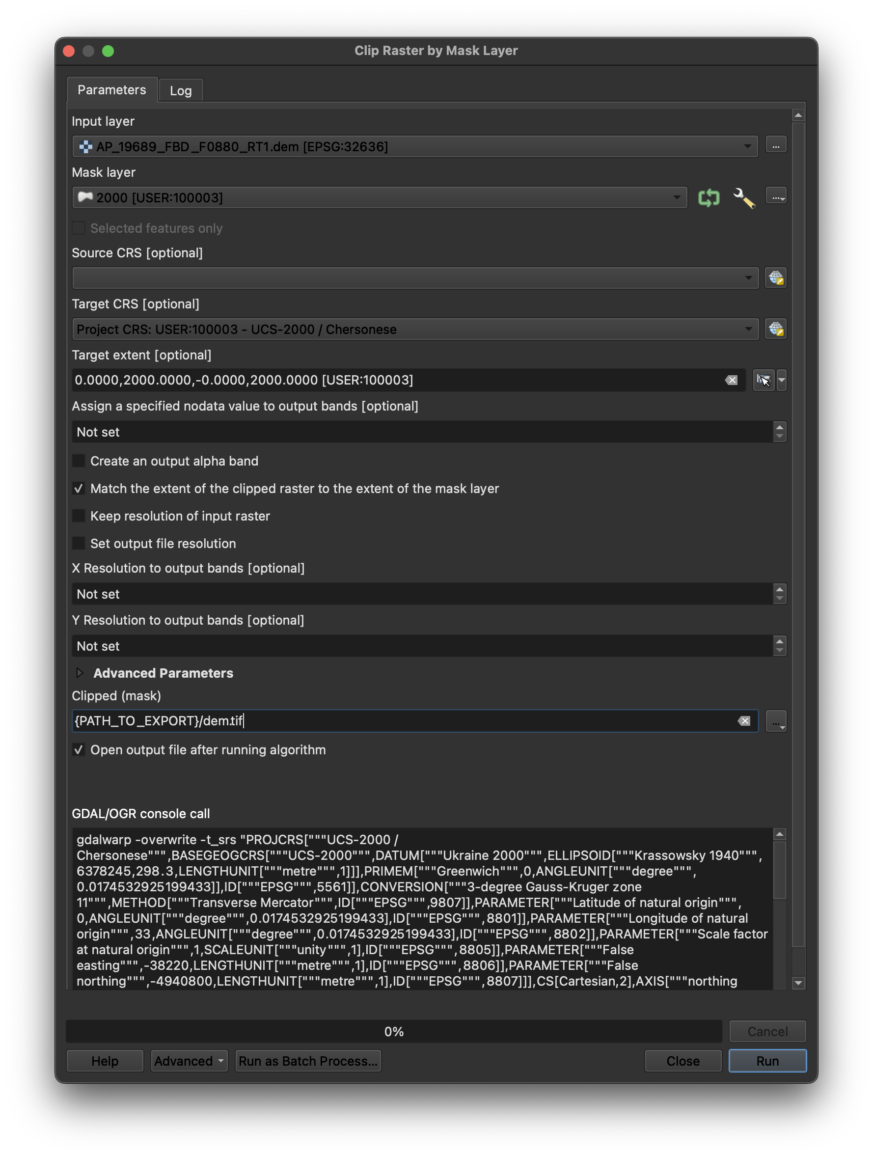
Clip Raster by Mask Layer. Properties for TIFF-souce layer
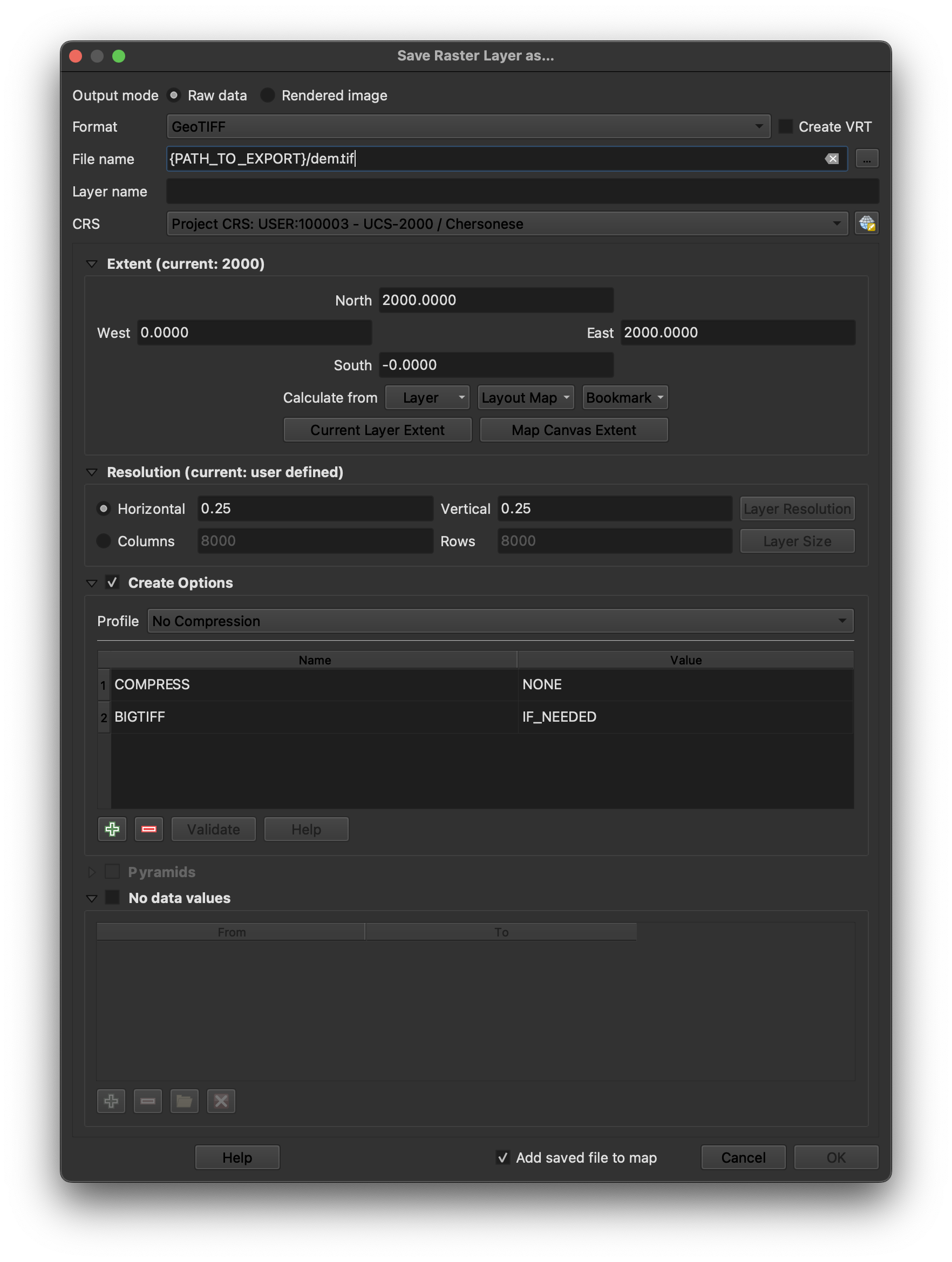
“Export” > “Save As”. Properties for XYZ-raster-tiles-source layer.
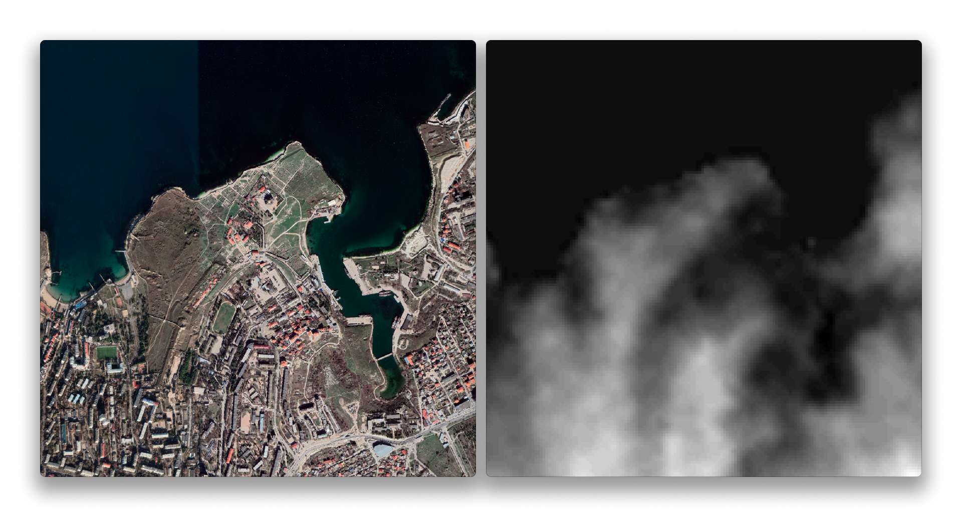
Exported Satellite and DEM raster.
Building Mesh model with Blender
Now that we have DEM and satellite imagery prepared, we can start building a 3D mesh model using Blender and the BlenderGIS add-on.
1. Start new blender project (don't forget to download, activate and configure Blender GIS plugin).
Setup custom CRS with Proj4 string:
+proj=tmerc +lat_0=0 +lon_0=33 +k=1 +x_0=-38220 +y_0=-4940800 +ellps=krass +units=m +no_defs +type=crs
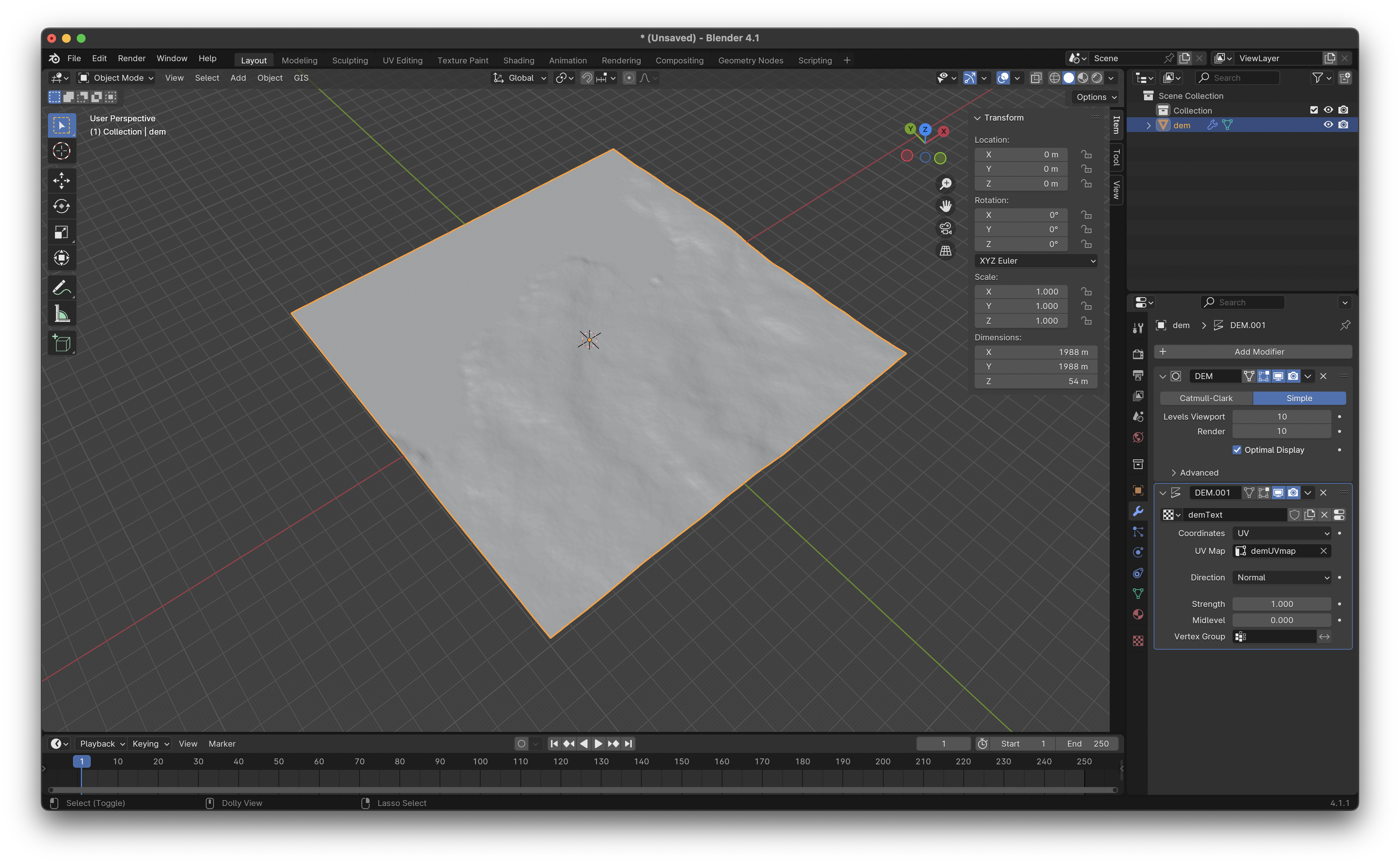
2. Build mesh using GIS > Import > Georeferenced raster
• Mode - DEM as displacement texture
• Subdivision - Subsurf
• Smooth relief = TRUE
• CRS - pick custom CRS
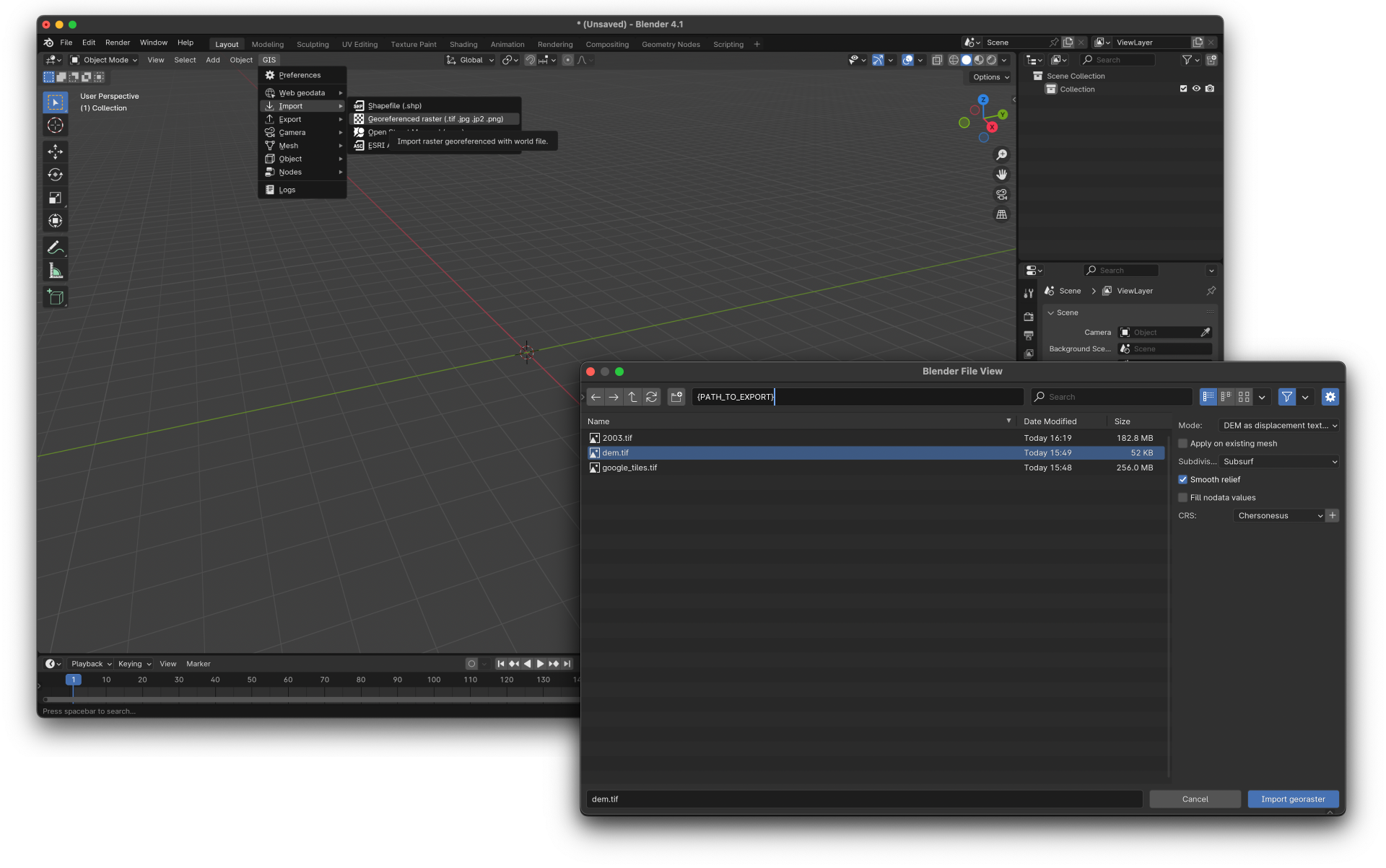
Load DEM as base texture for building mesh model
3. While we have model loaded and generated, we can adjust sharpness increasing or decreasing Subdivision Levels from Select Mesh > Modifiers > Subdivision Surface properties > Levels Viewport/Render
Control model sharpness
4. Check Georeference:
• Go to 3D View > View > Geoscene > Scene Georeferencing.
• Set the CRS to your custom CRS.
• Set X=0 and Y=0 to match the Blender scene’s origin to your custom CRS.
• Smooth relief = TRUE
• If you’re using a global or regional CRS, you can configure offsets to ensure alignment between your 3D model and the GIS data.
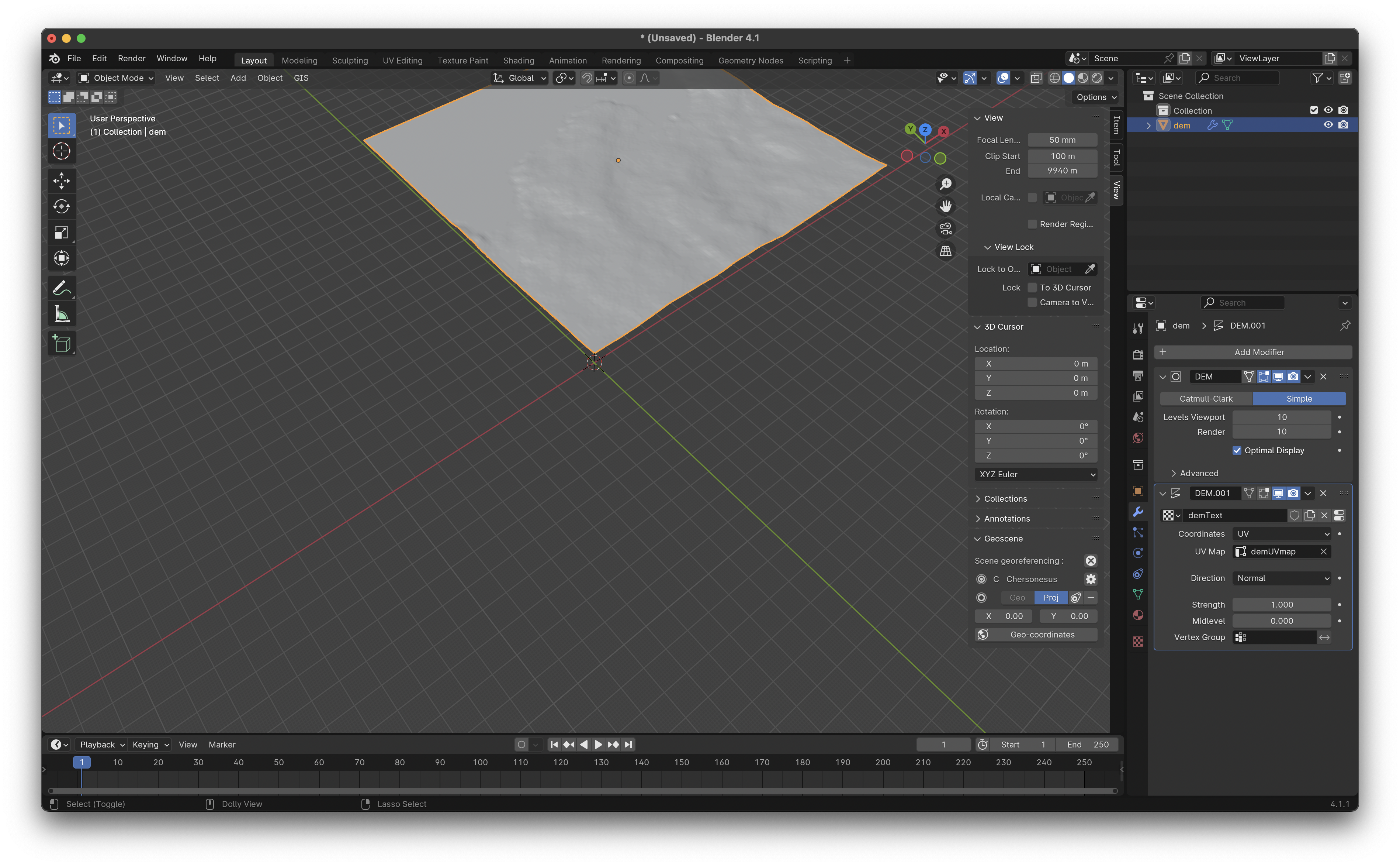
Configure Blender ↔ CRS offset
5. Load satellite imagery georaster as mesh texture basemap using GIS > Import > Georeferenced raster :
• Mode - Basemap on mesh
• Object - Provide mesh
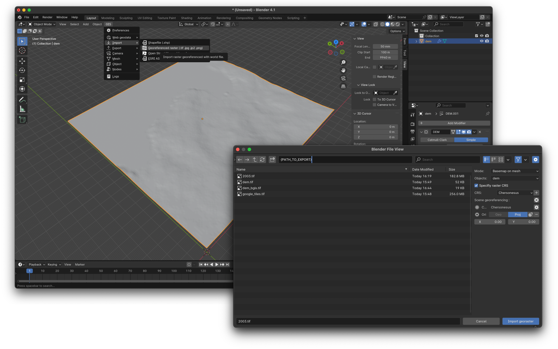
Load satellite imagery georaster as mesh texture basemap
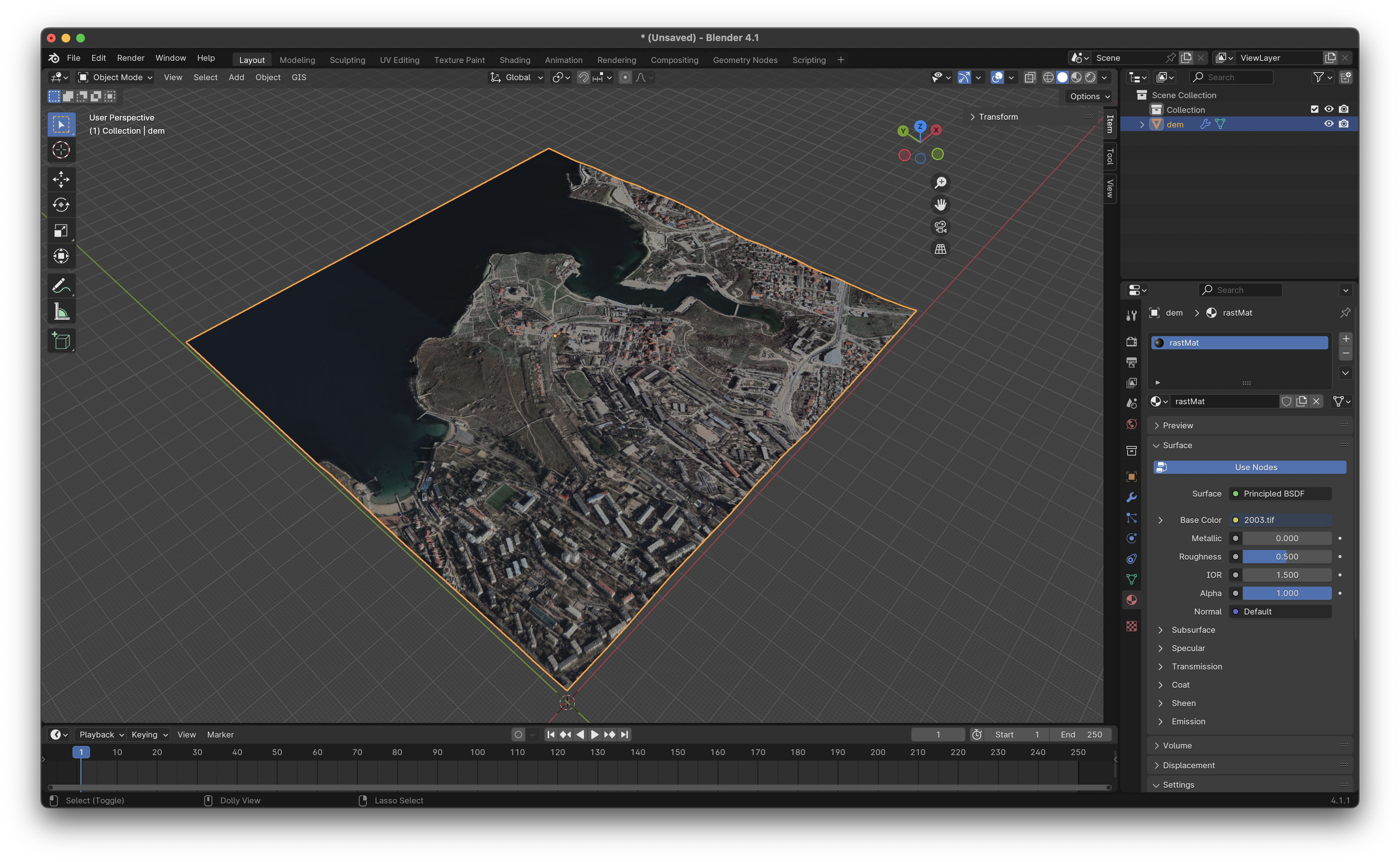
Textured 3D model
Alternative Methods to Build the Base Model
For users who don’t require highly precise georeferencing, configuring custom CRS or who need a faster workflow, there are other methods to create a 3D base model:
1. BlenderGIS with SRTM and Google Basemap Data:
• If high-resolution DEMs aren’t needed, you can use BlenderGIS to import SRTM data directly within Blender. This method is faster but less accurate.
2. Create 3D Context Maps with QGIS and Speckle
• Similar to QGIS→Blender workflow, but use Speckle as geometry processor and storage.
Image-Matching
Image matching aligns 2D images to a 3D model using the Perspective-n-Point (PnP) method. This approach determines camera extrinsics (position and orientation) and ***intrinsics*** (lens characteristics like focal length and distortion).
PnP works by matching multiple 2D points with their corresponding 3D points. Solving these relationships allows us to determine the camera's 3D position and estimate internal parameters.
To solve camera extrinsics with known focal length, you need at least 4 points. If you want to automatically determine the focal length, optical center, and lens distortion (camera intrinsics), you need at least 6 points. For more details, see OpenCV's solvePnP and OpenCV`s camera calibration documentation.
Solve Static Image camera position
1. Install the Image-matcher Blender add-on following the initial instructions.
2. Split the Blender screen by dragging the top left corner of the 3D view until the mouse cursor turns into a cross. Click and drag to the right to create a split-screen. This allows you to view both the 2D image and 3D model side by side.
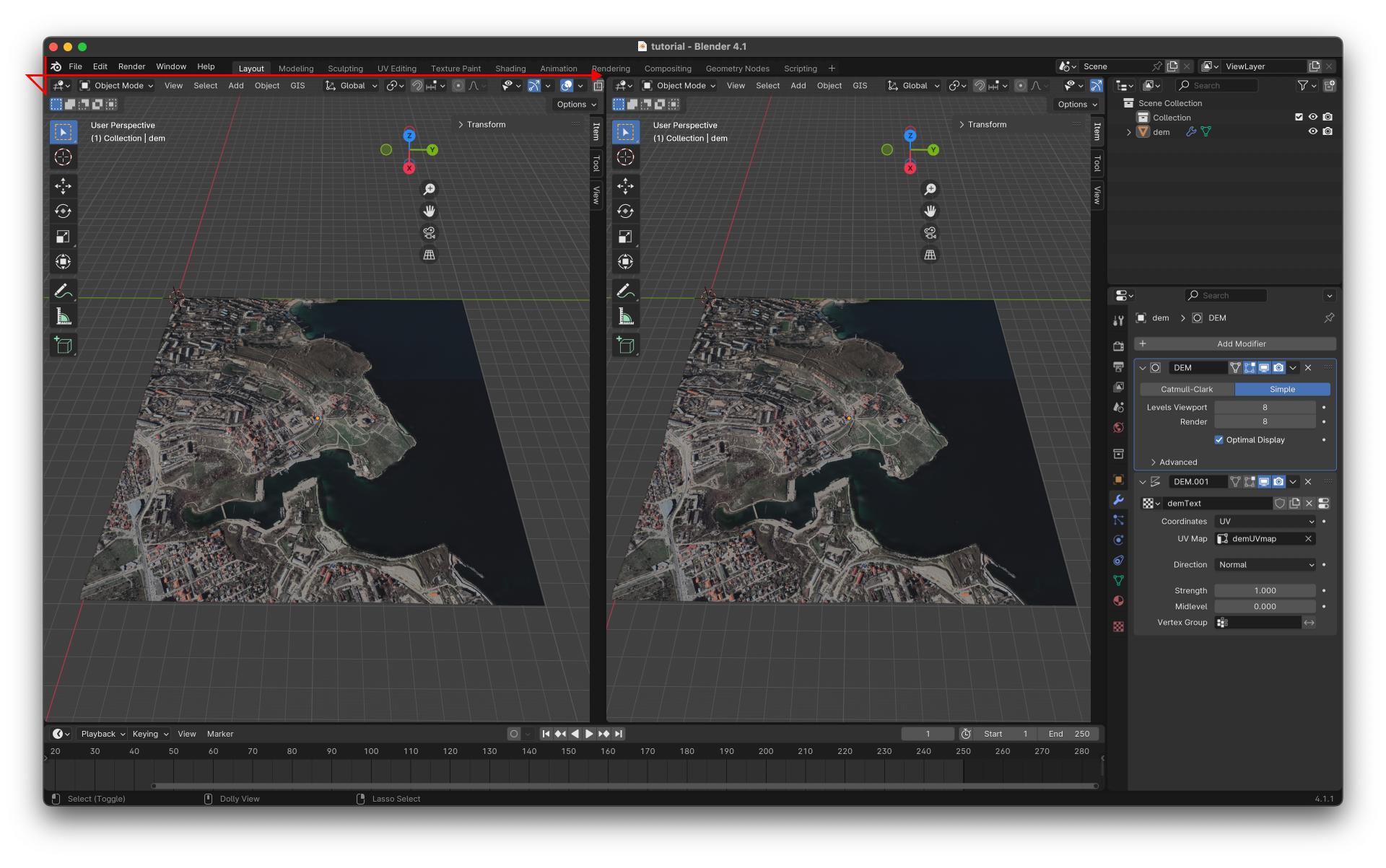
Split Blender screen
3. Change the Window editor type to 'Movie Clip Editor' for one of the windows you created. Click on the icon in the top left corner of the newly split screen, and select 'Movie Clip Editor'.
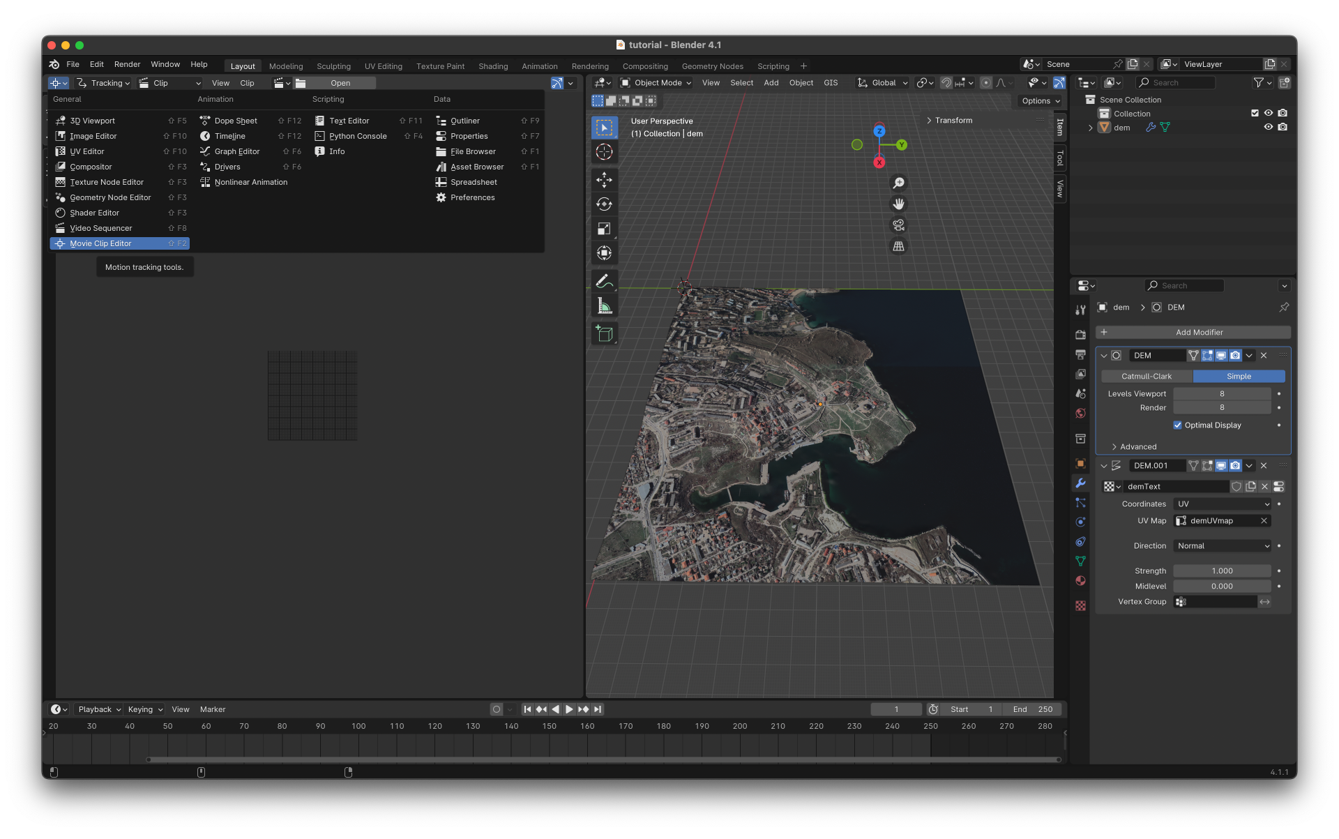
Change Window editor type to Movie Clip Editor
4. Add Image Go to Image Match > Define Image Filepath > pick image and click Accept > Click Add Image
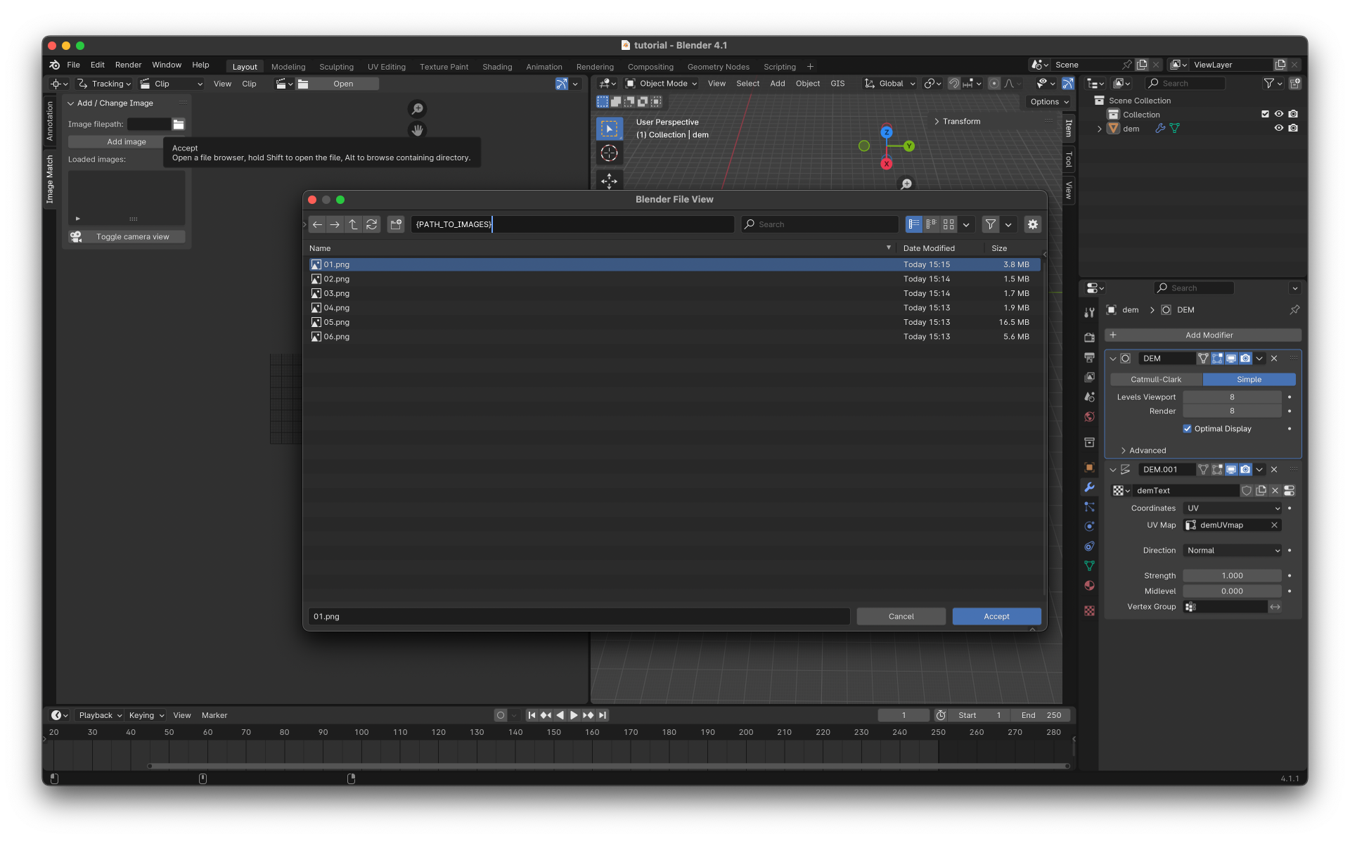
Select and load Image
5. Pick 3D Model and Select Points
• Go to the Points Tab > Use the dropdown to select your 3D model or click the eyedropper icon to pick it directly in the 3D viewport.
• In Point Mode, left-click in the 2D image to add a point, and then select the corresponding point on the 3D model in the 3D viewer.
• Repeat this process until you have at least 6 pairs of points (or 4 pairs if you know the focal length or plan to adjust it manually).
• Ensure that the points are distributed across the entire image plane for better accuracy. To exit Point Mode, right-click or press Esc.
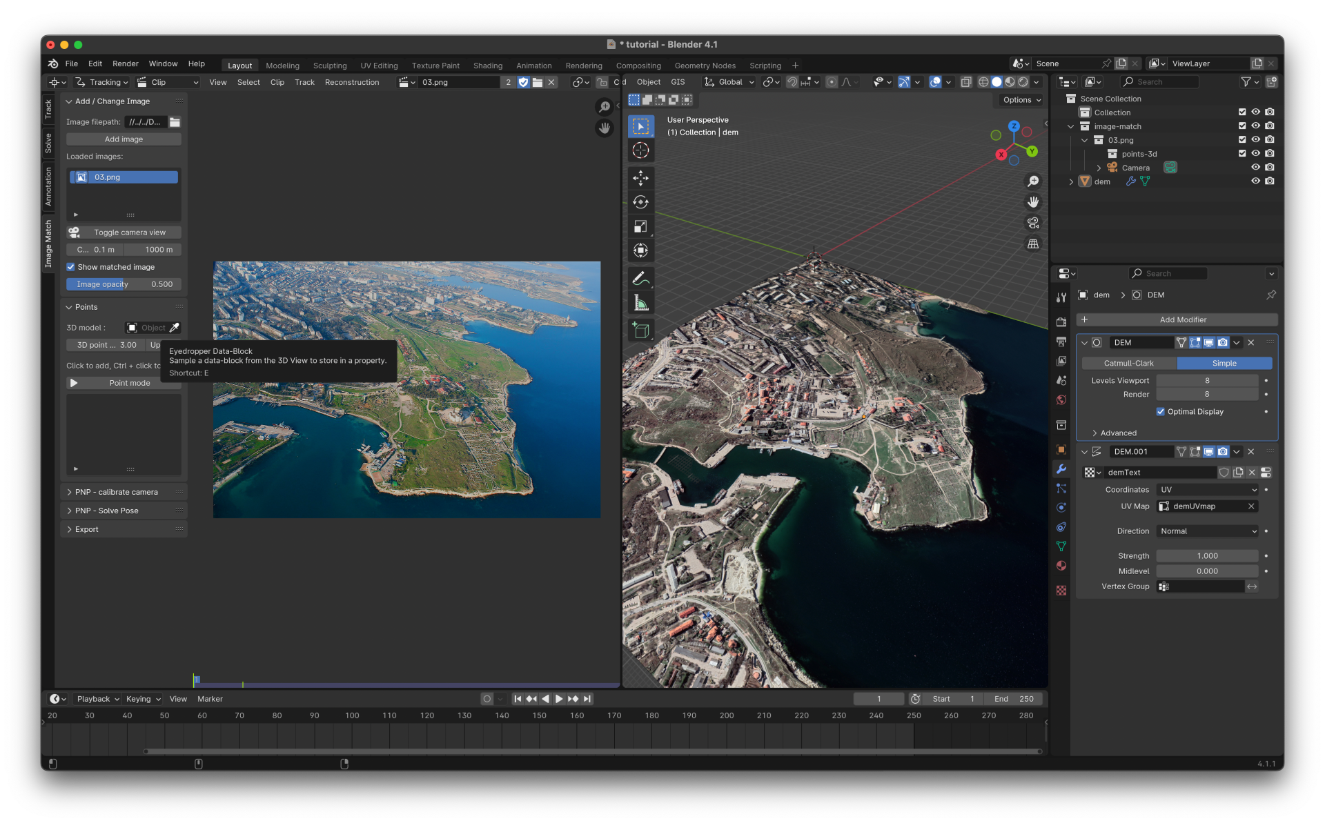
Pick 3D Model

Select corresponding points pairs
6. Camera Calibration (PNP-Calibrate Camera Tab)
• Calibrate the camera settings (e.g., focal length) using OpenCV.
• If you know the focal length, input it directly. Otherwise:
⸰ Tick Focal Length and click Calibrate Camera.
⸰ Check Reprojection Error; lower values are better.
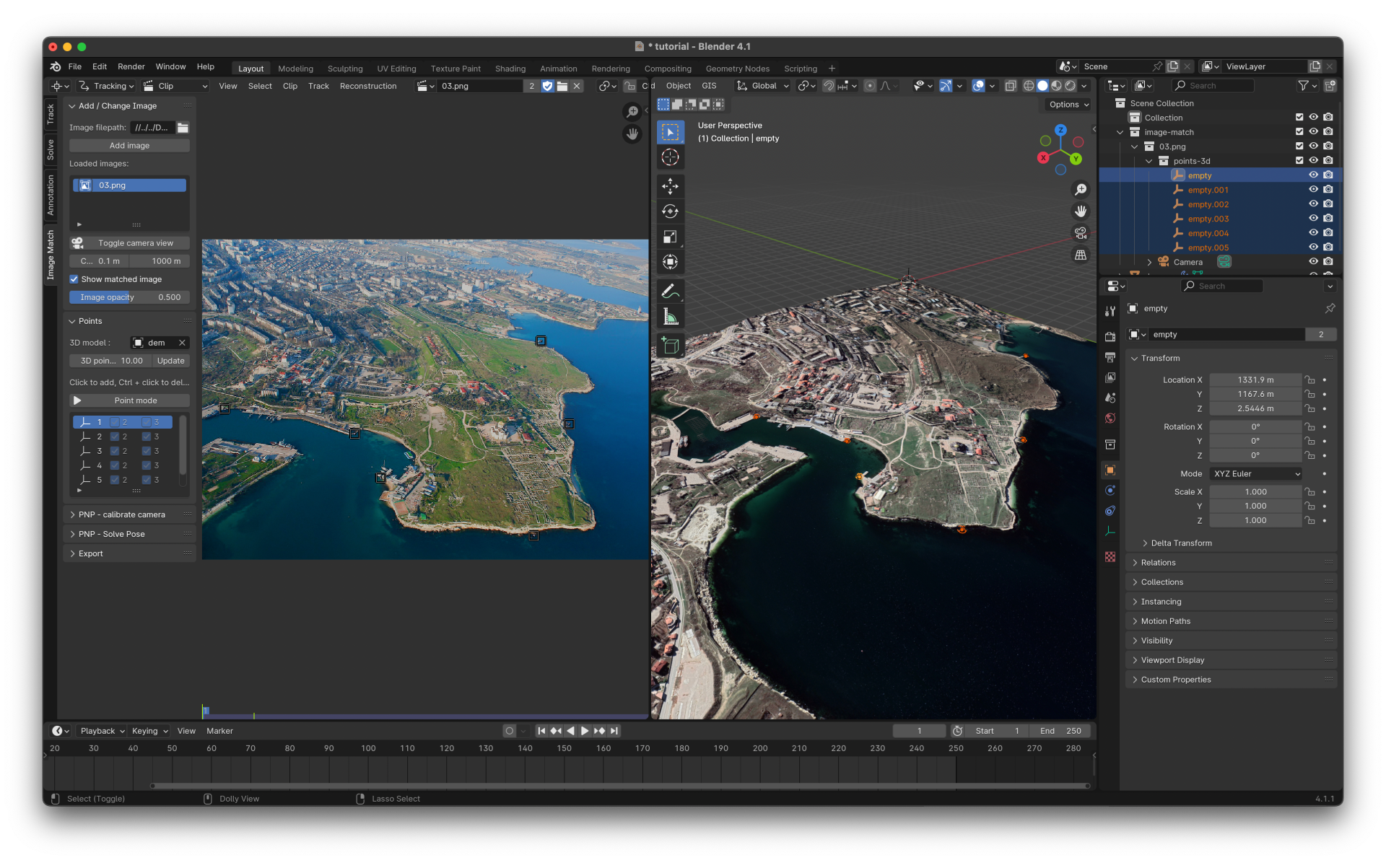
7. Solve Camera Pose (PNP-Solve Pose Tab)
• Click Solve Camera Pose to calculate the camera's position and orientation.
• Use Toggle Camera View to see the match.
⸰ Adjust image opacity and toggle the 2D image for better visualization.
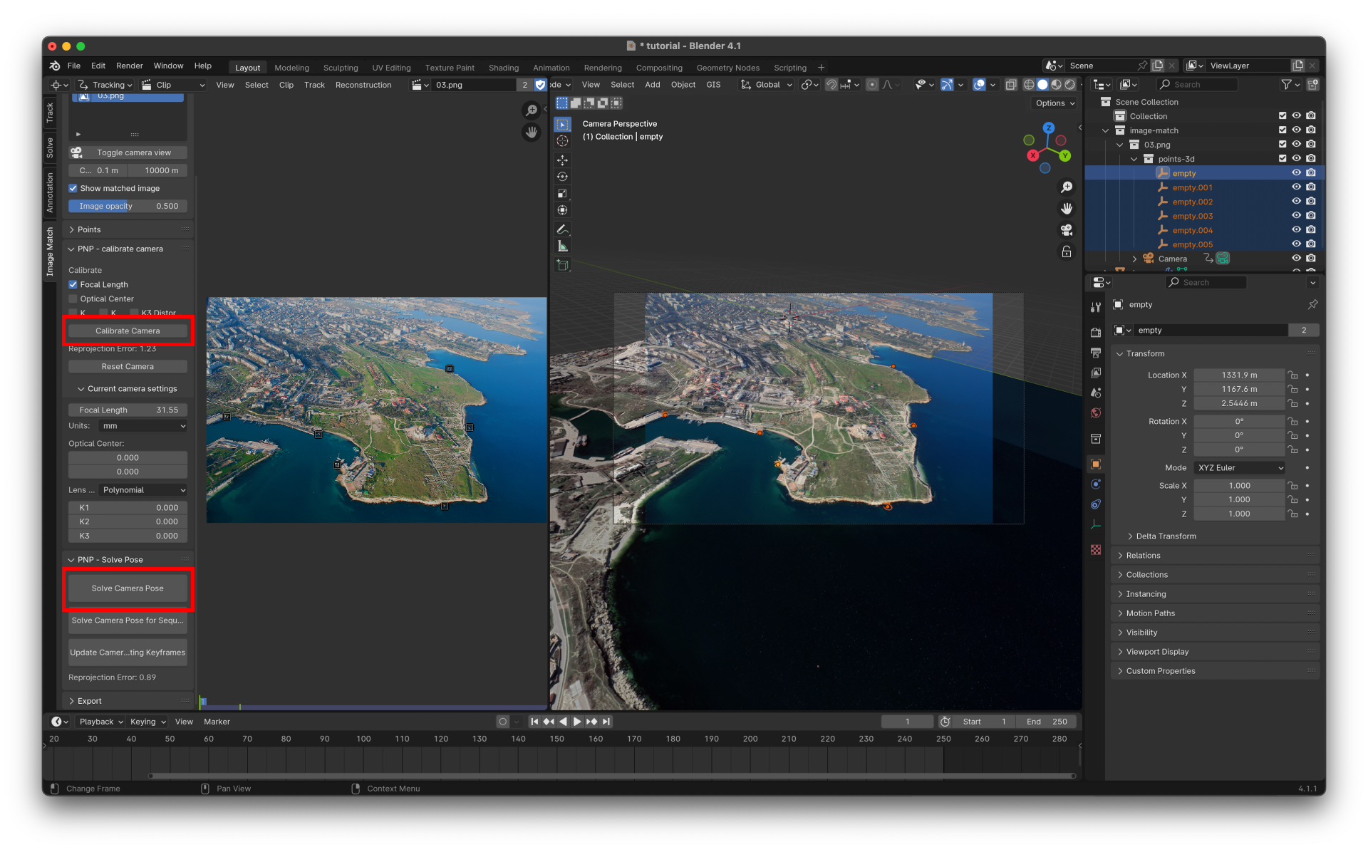
Calibrate and solve camera
8. Add more images
• Switch between images by clicking the blue highlighted icon next to their names.

Troubleshooting a Bad Match
• Check Point Pairs: Ensure points are accurately placed in both the 2D and 3D
• Spread Points Evenly: If the match is bad in specific areas, add more points there.
• Recalibrate Camera: Click Reset Camera, then Calibrate Camera again, and re-solve the pose.